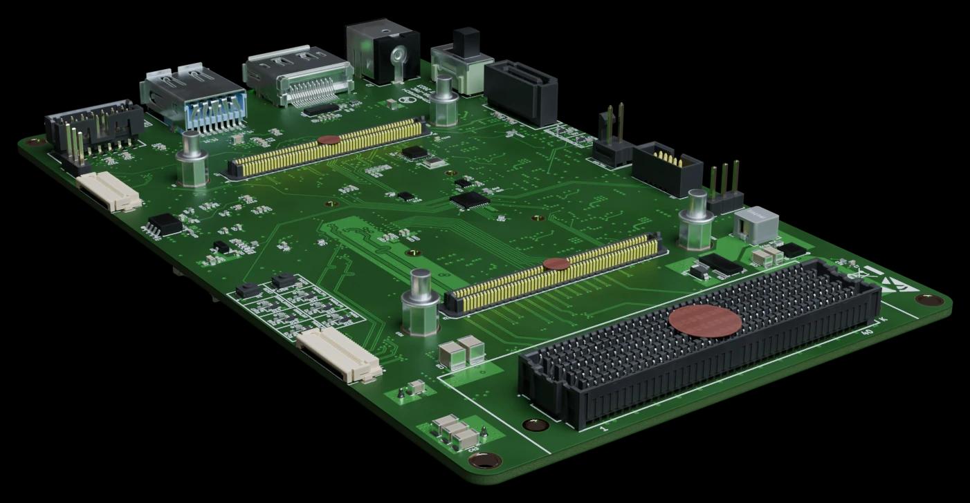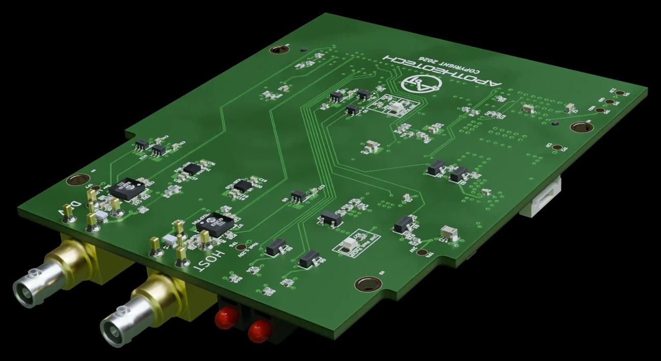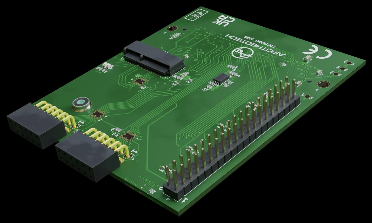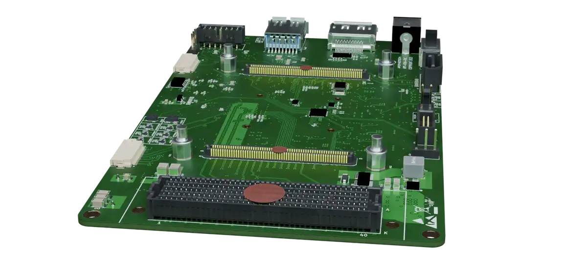
Aper-Oculus, a Kria K26 carrier board designed by ApotheoTech

Camera hardware, FPGA logic and Linux drivers, from one bench.

ApotheoTech is an engineering company in Orlando, Florida. We design imaging systems end to end: the sensor board, the FPGA design behind it and the driver that hands frames to your software.

Three services that cover the whole camera

The hard bugs in a camera sit between the board, the FPGA and the driver. ApotheoTech takes all three on a project, so a fault can be followed from one into the next.

Custom camera design

Sensor board

Image sensor
Sensor clocks
Power rails

Processing board

FPGA design
SLVS-EC receiver
Binning and ROI
Camera link output
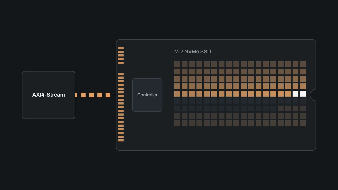
NVMe recording
DDR4
M.2 SSD
Supervisor MCU
Linux drivers

Host computer

PCIe DMA
V4L2 driver
/dev/video0
Your application
Block diagram of a camera system. Custom camera design covers the sensor board and the processing board. FPGA design covers the logic inside the FPGA: sensor receiver, image processing, camera link output and recording. Linux drivers cover the host computer: PCIe DMA, the V4L2 driver and the video device your application opens.
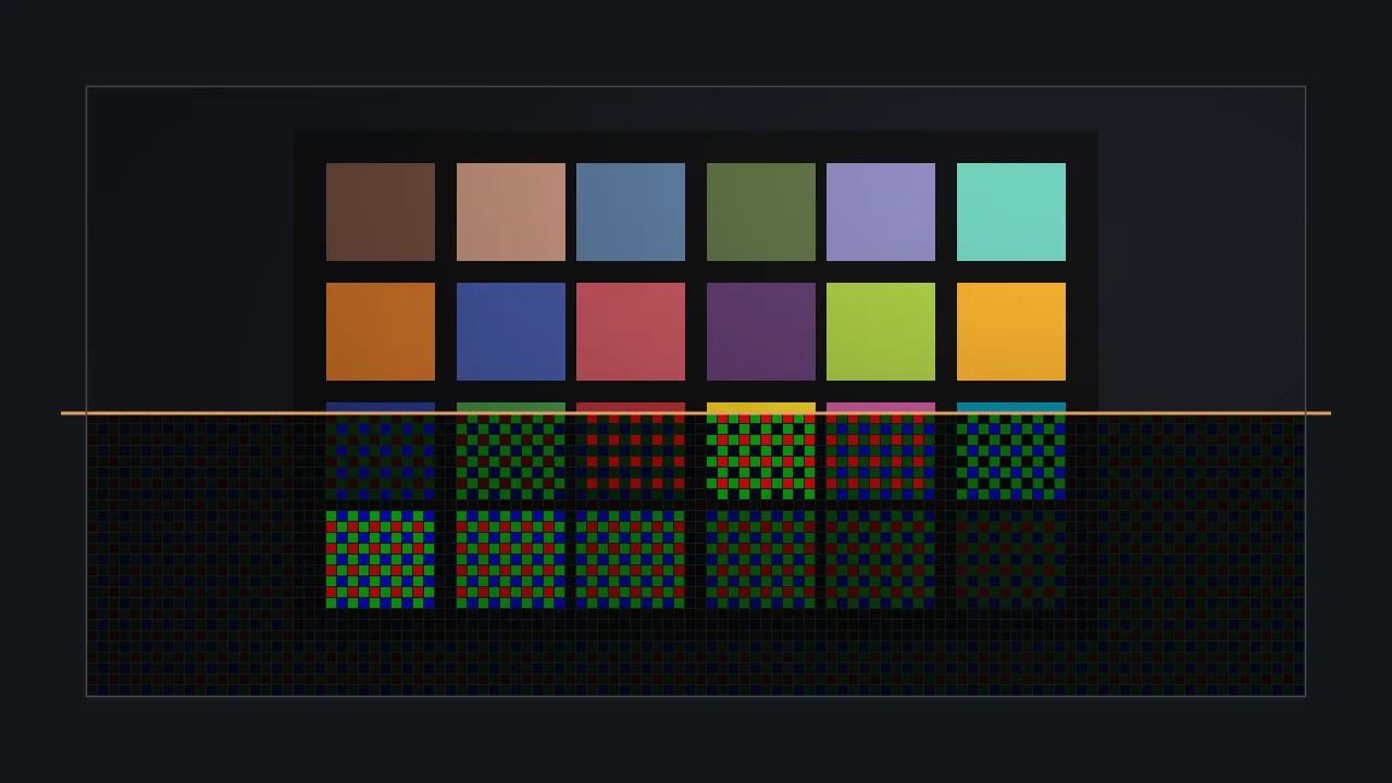
Bayer sensor data being turned into a color picture

Custom camera design

We design the camera around your sensor and your data rate: the sensor board, the processing board, the FPGA design and the host software, delivered as one working system.

Sensors
Sony SLVS-EC, proven on the IMX530, IMX547 and IMX421
Outputs
CoaXPress 2.1, 12G-SDI, PCIe, NVMe recording
Boards
Up to 32 layers, with DDR4, PCIe and large BGAs
How a camera project runs

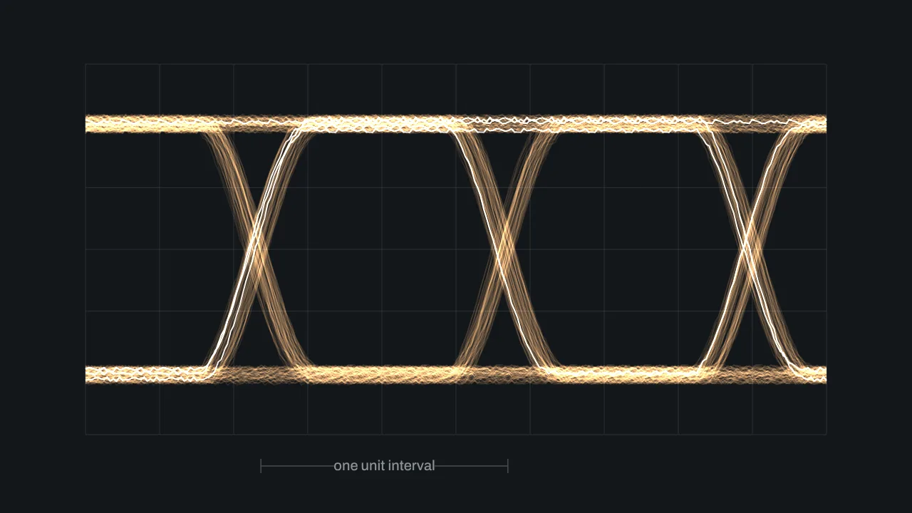
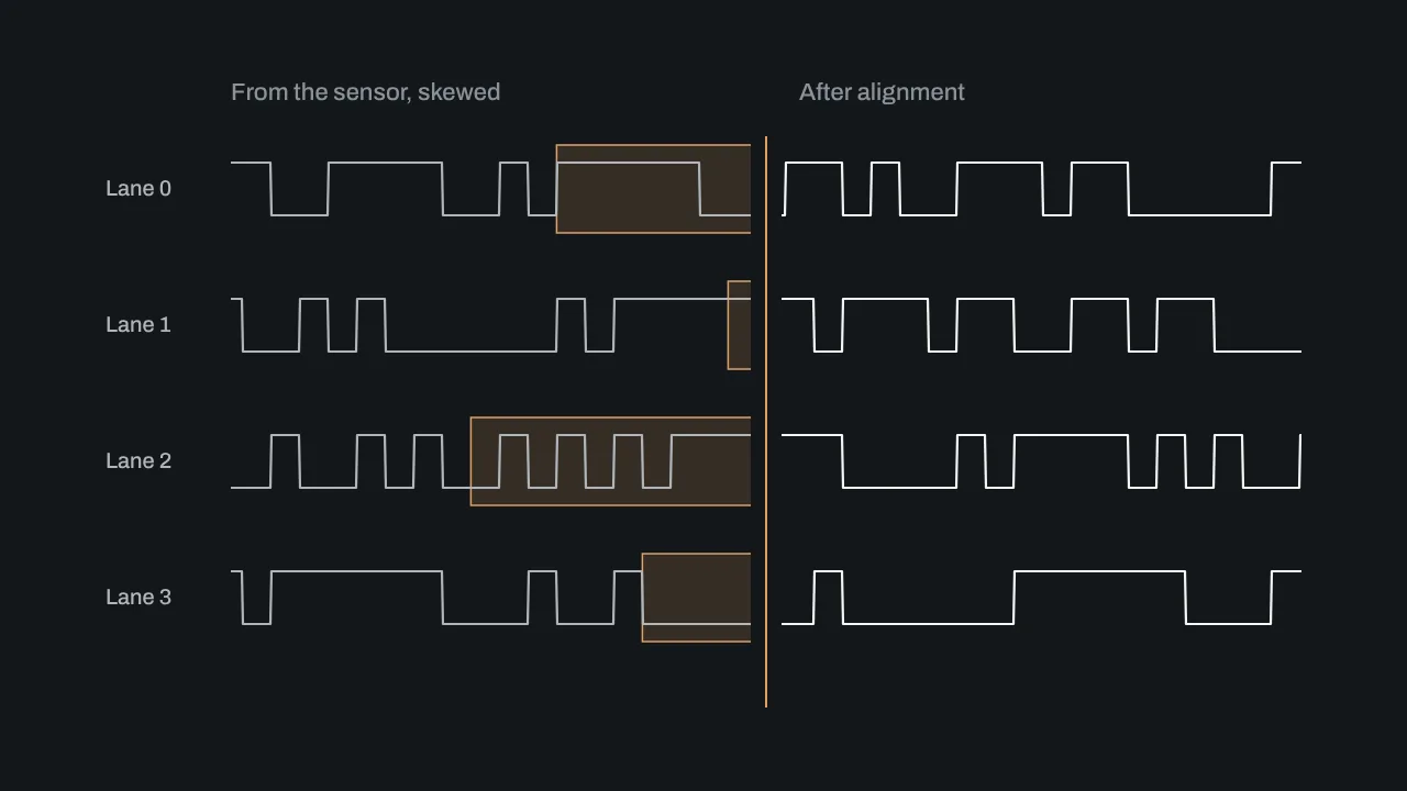
Four serial lanes arriving skewed and leaving aligned

FPGA design

We write RTL from the specification for AMD FPGAs: sensor receivers, camera links, storage, and the transceiver work underneath them.

Our cores
CoaXPress 2.1 Host and Device, SLVS-EC RX, NVMe host
Transceivers
GTH, GTY and GTP, to 12.5 Gb/s per lane
Devices
Kria K26, Zynq UltraScale+, Kintex, Artix

FPGA design services

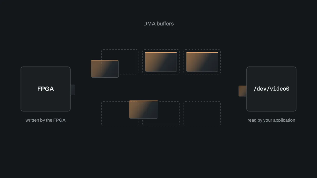
Frames moving from the FPGA through DMA buffers to a video device

Linux drivers

We write kernel drivers that make custom hardware show up as a standard device, so your software team keeps the tools it already uses.

Video
V4L2 capture with zero-copy DMA
Buses
PCIe, USB and character devices
Platforms
Jetson Orin, PetaLinux, Yocto, Ubuntu

Linux driver development

Also available on their own: high-speed PCB design, Jetson camera integration and embedded firmware.

ApotheoTech has built every stage of that path

Stage 1 of 6: sensor readout

SLVS-EC RX IP core

Receives Sony SLVS-EC image sensors at Baud 3, including the IMX530, IMX547 and IMX421. It runs on GTH, GTY and GTP transceivers, or on HP I/O when the transceivers are already in use. With AXI4-Stream out it uses 1,433 LUTs, 2,835 registers and 4 block RAMs.

Four serial lanes arriving skewed and leaving aligned
  1. Sensor readout
  2. Image processing
  3. Camera link
  4. Frame grabber
  5. Recording
  6. Host software

Recent work

8-channel 12G-SDI capture card

  1. 8 x 12G-SDI
  2. FPGA
  3. PCIe Gen3 x8
  4. V4L2 driver
  5. Application

ApotheoTech wrote the FPGA gateware, the PCIe DMA engine, the Linux driver and a sample application for an eight-input SDI capture card, as one project.

Read the case study

Inputs
8 channels of 12G, 6G or 3G SDI, rate detected automatically
Host interface
PCIe Gen3 x8 with a custom DMA engine
Software
V4L2 capture driver and a sample application
Schedule
12 weeks, architecture through commissioning

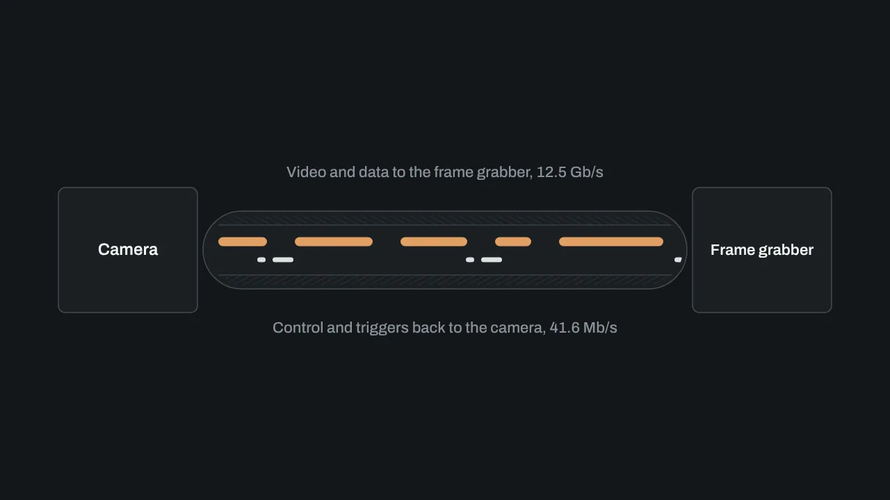
4-lane CoaXPress Host frame grabber

  1. CXP-12 camera
  2. 4 coax lanes
  3. FPGA
  4. PCIe
  5. Host

A frame grabber, designed here, that receives a four-lane CXP-12 camera and delivers it to the host over PCIe.

About the CoaXPress core

Camera link
CoaXPress 2.1, CXP-12 on four lanes
Host interface
PCIe
Built on
The ApotheoTech CoaXPress 2.1 Host core

Customer names are kept off this site.

How a project runs

  1. Step 1

    You describe the system

    The sensor or interface, the data rate, the FPGA or host you have in mind, and where the project stands today. A paragraph is enough to start.

  2. Step 2

    We ask questions, then send a scope

    We reply within one business day. The scope names what will be built, what it will be tested on and what you receive at the end.

  3. Step 3

    We agree a statement of work

    A fixed price when the deliverable can be defined up front, or time and materials while the requirements are still moving.

  4. Step 4

    We build it and bring it up

    Design, simulation and bring-up on real hardware. The FPGA, the board and the driver are debugged together.

Write-ups from bring-ups and debug sessions

Start with a paragraph about your system

Say what the sensor or interface is, how fast the data moves and what it has to reach. We reply within one business day.

Open the contact form

ApotheoTech LLC

Orlando, Florida

info@apotheotech.com